Spridget - The Story So Far...

Post pictures and stories about your cars both present and past. Also post up "blogs" on your restoration projects - the more pictures the better! Note: blog-type threads often get few replies, but are often read by many members, and provide interest and motivation to other enthusiasts so don't be disappointed if you don't get many replies.
Message
Author
Spencer
Posts: 24
Joined: Tue May 31, 2011 6:23 am

Re: Spridget - The Story So Far...

#21 Post by Spencer »

Still working on the LH side, need to finish the inner sill before I can fit the outer sill, which is the next thing I want to get out of the way:

Image

Again I could have replaced the whole inner sill but the centre section is fine and totally removing the inner sill has too much potential to put things out of line, repair section used is from a full inner sill.

Image

Welded and tidied up a bit

Image

Also the footwell side needs to be in place before the outer sill can be attached, just getting the basic shape correct:

Image

The footwell side joggled and ready to go in:

Image

Finish seam and plug welded, just needs linishing

Image

Cheers
Spencer
Posts: 24
Joined: Tue May 31, 2011 6:23 am

Re: Spridget - The Story So Far...

#22 Post by Spencer »

One part of the project which seemed to take an age was the drivers door, mainly because I hadn't repaired a door before, nor fitted a door skin so I think I just kept fixing the frame until I couldn't put off fitting the door skin any longer:

I started by linishing the whole of the drivers door back to the metal, which in hindsight was a waste of time, but at that stage I was still considering maybe repairing the skin:

Image

Most of the rust damage has occured where the door seam is or it is double skinned against the frame, perfect moisture traps:

Image

Image

Some heavy pock marking under where the quarterlight fits, again a moisture trap:

Image

Another feature of Spridget doors is the fact they always crack in two places, the first shown here is near the rear edge of the quarterlight:

Cut through the crack to clean the edges:

Image

And I have fixed a 2mm thick spreader plate which spans the crack and drilled holes which will be plug welded in an attempt to reinforce this area.

Image

And welded, just needs linishing:

Image

Linished:

Image

Hopefully this will stop the crack coming back or it may just result in the crack moving to the edge of the new stiffer area, but if it fails I have just lost the half hour spent on it.

Cheers
Spencer
Posts: 24
Joined: Tue May 31, 2011 6:23 am

Re: Spridget - The Story So Far...

#23 Post by Spencer »

So as I suggested the door repairs were a bit of a marathon:

The bottom of the door was heavily pock marked, but probably more than capable of surviving a few more years but it seemed pointless not to fix it at this stage:

Image

Image

Part way through making a repair section, still not quite the right shape:

Image

And also replaced the whole of the lower section which is shown in place here:

Image

And then the edges which formed the moisture trap for the rust which was visible on the door skin:

Image

Image

Finshed:

Image

And then attention turned to the other crack which develops:

The rear of the window glass opening:

Image

Same idea as the other crack, add some material which hopefully strengthens this area:

Image

The door frame ready for a new skin...

Image

Cheers
Spencer
Posts: 24
Joined: Tue May 31, 2011 6:23 am

Re: Spridget - The Story So Far...

#24 Post by Spencer »

Modified the door frame a little further (another delaying tactic to actually putting the damned door skin on:

Image

But I really have to start now, As mentioned I haven't done this before so I have shown the tools I used incase it is of use to others:

Image

The dolly in particular being less than ideal as it is too short and all to easy to dig in to the skin face, but it's all I have:

Image

Dug around on the internet as regards what to use as a seam sealer / structural adhesive, the purpose being to try and keep further moisture out of the seams (unlikely but worth a try) and improve the rigidity of the finished unit, mainly due to the fact it was all I could lay my hands on locally I chose Tiger seal, so a bead was applied around the mating surface

Image

The use of adhesive made the job all the more manic as I was worried it would set before I had the skin properly in place...

I used the quarterlight holes as a means of holding the two halves together, which hopefully also meant it was in the correct poistion

Image

This is the area on the door skin which corresponds to the second crack I showed in the previous post, so just preparing it for the same spreader detail:

Image

Mole grips were used to folds Inaccessible areas

Image

The edges have now been hammered over:

Image

I used about 10 passes per seam, trying not to fold too much over at one time an distorting things

The area where the door handle is fitted is the only radius area of the skin, so I decided to make a cut in the door skin return so it could be folded in two parts - Mistake...

Image

Although it looks innocent enough from this side it created a small 'dink' in the outer surface which will need attending to:

Image

The rest of the skin looked pretty good and should only need light filing to remover any slight bruises and not require any filler

Image

Quarterlight area finished welded / linished:

Image

And the other crack site has been welded and linished, the whole area was built up slowly with weld so I don't need to use filler in this area as it will easily crack

Image

Cheers

Anyway back to the outer sill...
Spencer
Posts: 24
Joined: Tue May 31, 2011 6:23 am

Re: Spridget - The Story So Far...

#25 Post by Spencer »

Finished preparing the inner sill, which has been primed and painted:

Image

Outer sill trial fit, door fitted to check alignments:

Image

Outer sill finish welded and plug welds linished

Image

Not sure what to tackle next, but should get at least another day on it this weekend

Cheers
rich.
Posts: 6898
Joined: Wed Jan 05, 2011 9:18 pm

Re: Spridget - The Story So Far...

#26 Post by rich. »

tidy job..
User avatar
JPB
Posts: 10319
Joined: Fri Jan 07, 2011 3:24 pm

Re: Spridget - The Story So Far...

#27 Post by JPB »

Aye, very tidy. You're a bit useful at the welding - that job's pure art in sheet metal form.
Definitely nicer to behold than the unmade beds and the halved cae of the art world.
J
"Home is where you park it", so the saying goes. That may yet come true.. :oops:
Spencer
Posts: 24
Joined: Tue May 31, 2011 6:23 am

Re: Spridget - The Story So Far...

#28 Post by Spencer »

Thank you for the very kind comments :D

I wish it was worth as much as the unmade bed ;)

The finicky detail things seem to take longer than fitting things like sills, these few jobs did take longer than the outer sill

I don't want to use filler an areas like the door shuts, the B pillar to sill area required some improvisation to get at to linish it which involved the use of a die grinder amongst others

Image

Next will be filling the gap between the outer sill and the footwell

Image

Cheers
Spencer
Posts: 24
Joined: Tue May 31, 2011 6:23 am

Re: Spridget - The Story So Far...

#29 Post by Spencer »

Token jesture from yesterday, but having the house painted hindered progress ;)

Image

But it feels like a milestone has been reached now as I have finished the Inner and outer sills on both sides, toeboards, footwells, all of which lets me move the shell around when I am ready to do the rear and the underside, hopefully all on a rotisserie without fear of twisting the chassis

Cheers
Spencer
Posts: 24
Joined: Tue May 31, 2011 6:23 am

Re: Spridget - The Story So Far...

#30 Post by Spencer »

In order to improve ground clearance I am trying to fit the front anti roll bar above the chassis leg,

The first look see:

Image

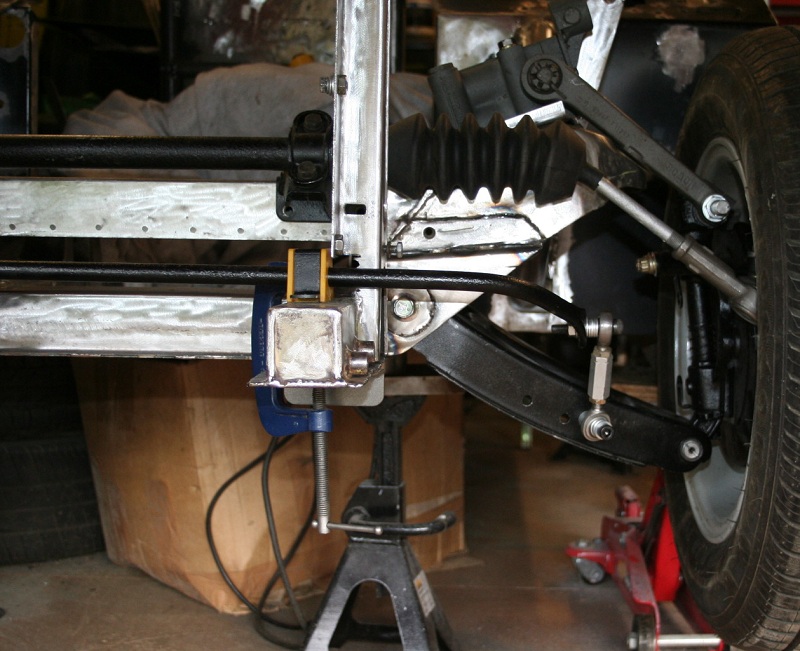
The LF suspension and road wheel is fitted to check for clashes and to move the suspension from full droop, through ride height and in to full bump.

Image

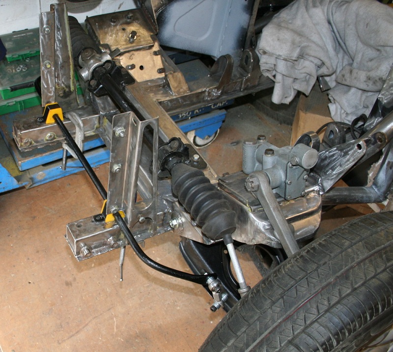
One big problem when fitting an anti roll bar in a custom position is the drop links necking out and creating side loads or other undesirable affects

I plan on fitting an adjustable (spherical) drop link on one side and a std drop link on the other, at the moment this set up is good at full droop and ride height but starts to load the anti roll bar laterally at full bump so I need to experiment further with drop link length and angles to make sure there are no side loads applied throughout full suspension travel.

Started to seal and etch prime the bits I have already done as things need to be tidied up, I have put the thinnest 'smear' of seam sealer to the welded joints. Initially I brushed the sealer in place but I ended up applying it like you would if you were sealing a bath.

I preferred how it looked before the seam sealer better but realise it had to be done

Image

Image

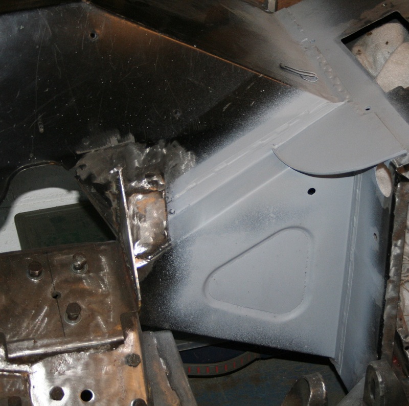
Can you tell what it is yet?

Image

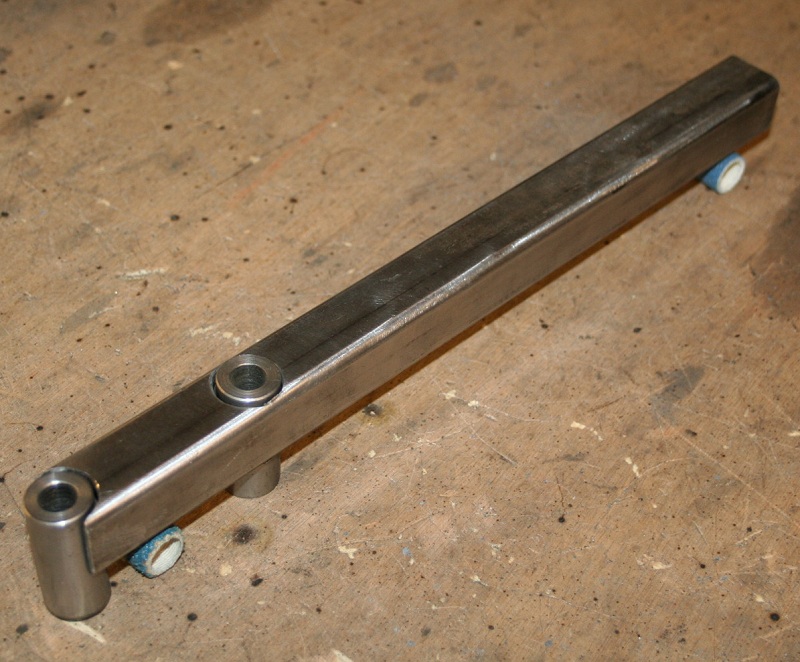
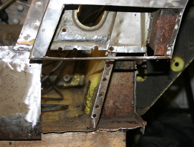
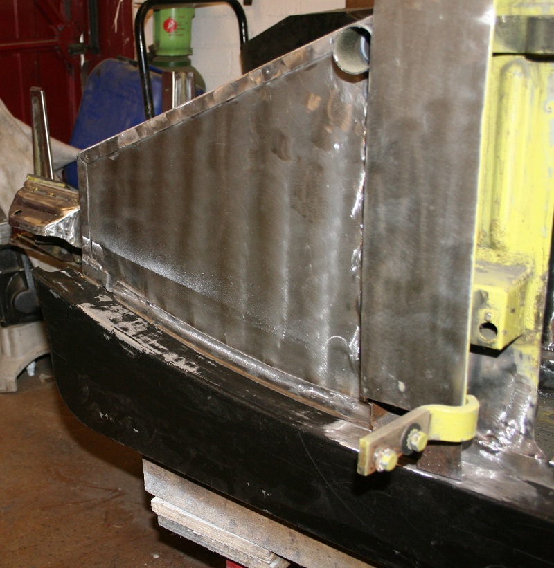
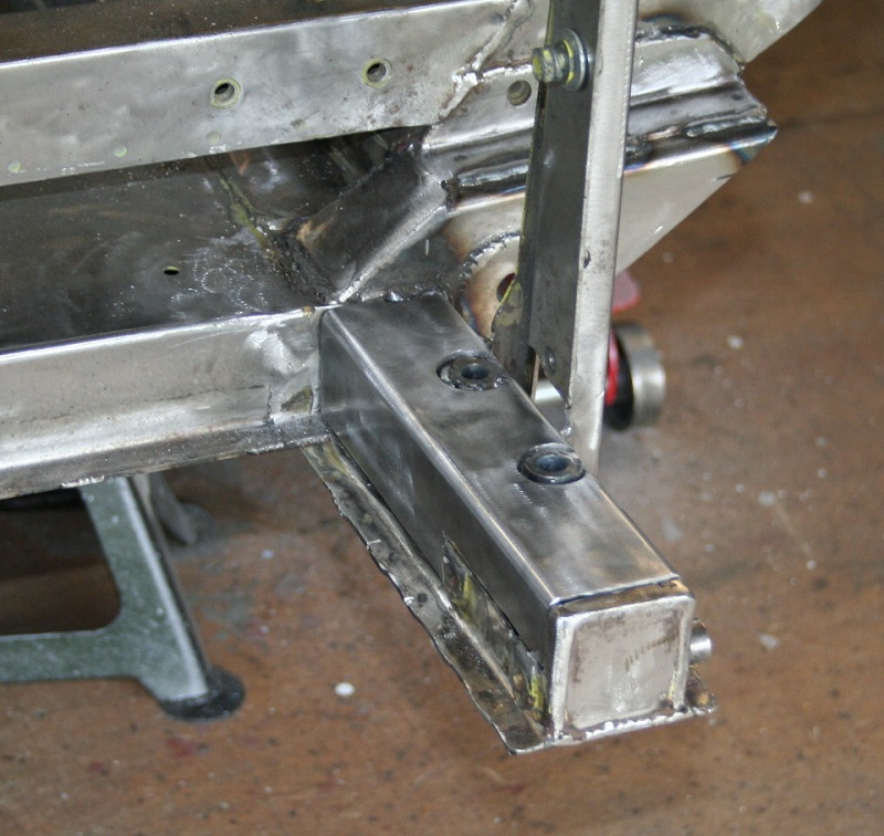
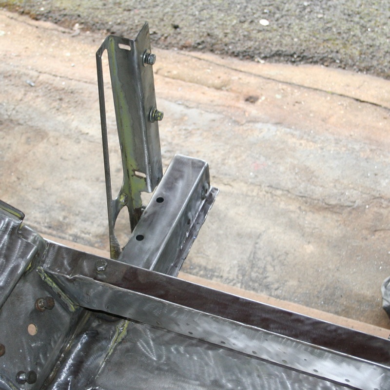
The work I have done previously on the front anti roll bar mounts was OK in terms of tidying the underside up but I want to tie the mounts better to the front crossmember.

The 25mm box section fits inside the main chassis leg and is tied to the chassis legs and the lateral crossmember


Image

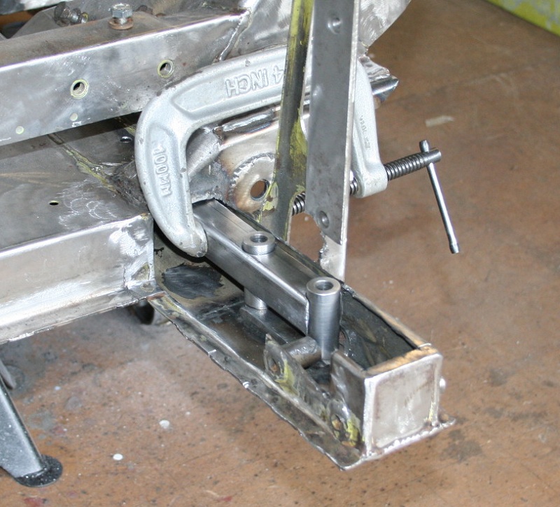
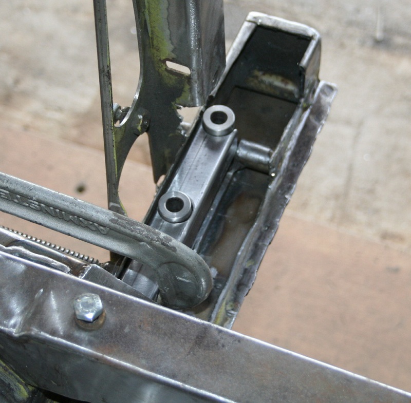
The two turned bushes will be welded to the box section and the existing threaded lower FARB mounting plate.

Image

Before everything was welded the front panel was fitted and two chassis legs were aligned and G clamped to minimise how much it moves when welded

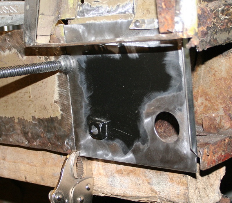
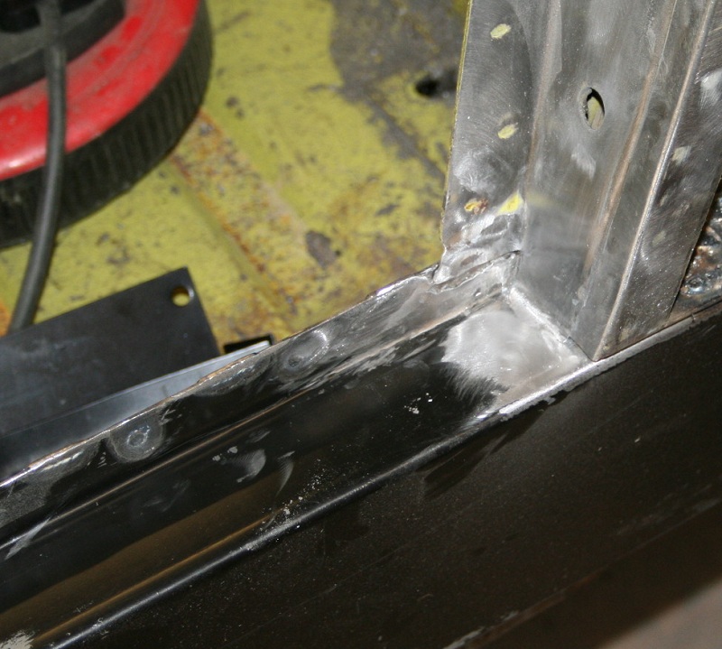
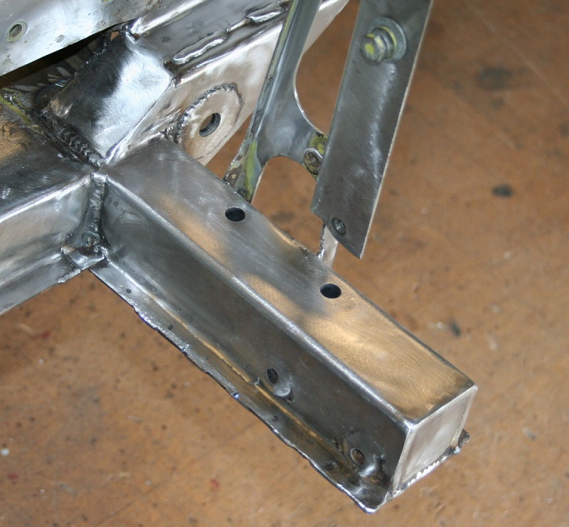
Tied to the tops of the chassis legs

Image

Tidied up a bit

Image

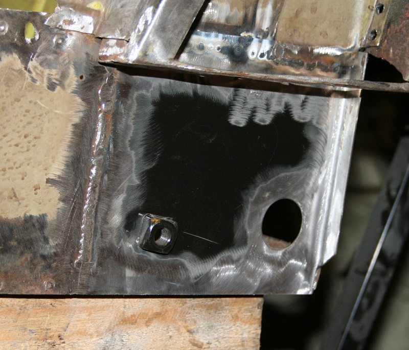
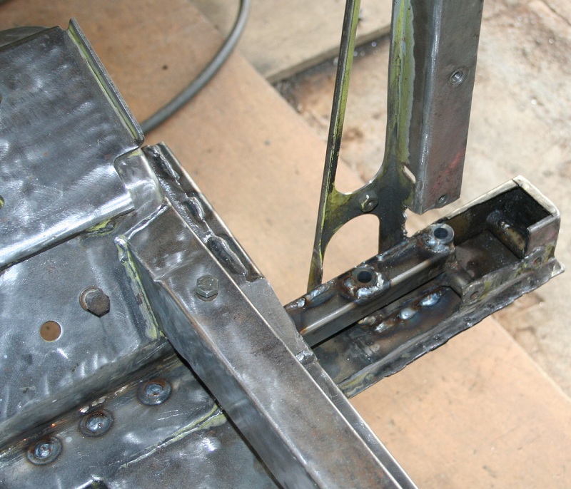
Plug / rose welds to the crossmember to the internal box section, these were 10mm holes to ensure the weld gets properly penetrated into the box section

Image

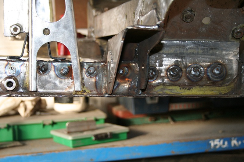
Just needs to have some internal plating and the external surface reinstated

These mounts allow me to fit the FARB above the chassis leg as previously shown but the original mounts still exist below so can be put back to standard but with improved location.

The difference it has made to the chassis leg stiffness ahead of the crossmember is really suprising considering the original chassis leg sections haven't yet been put back.

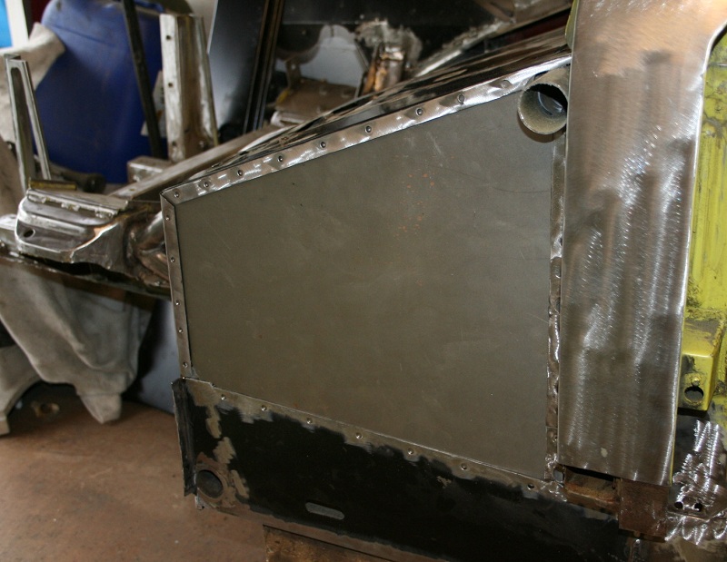
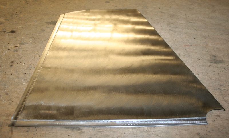
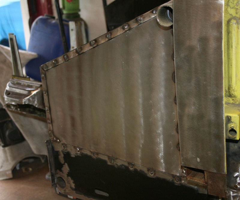
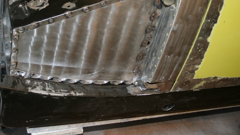
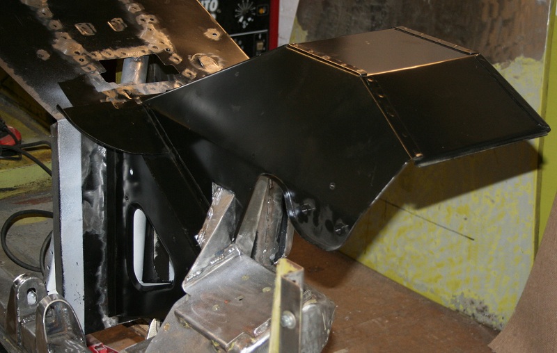
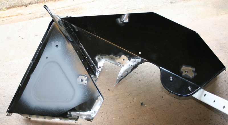
Also finished the LF mudguard / inner arch ready to weld in place, triangular openings again closed off.

Image

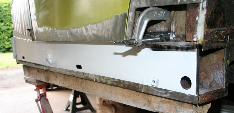
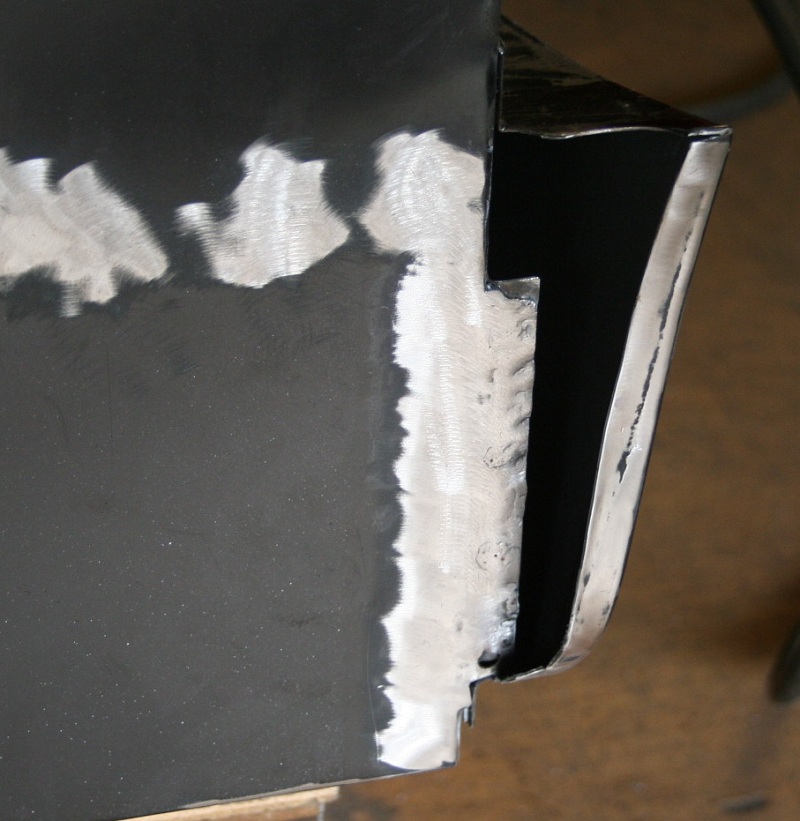
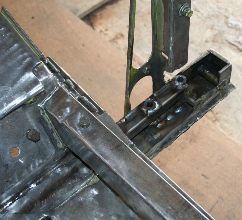
Replaced the outer skin of the front chassis leg after I had added a few more bits of internal stiffening, basically connecting the 25mm box to the lower skin of the original chassis leg.

Image

Welded an linished in place:

Image

Just the two holes give the game away as all else in now hidden again.

Image

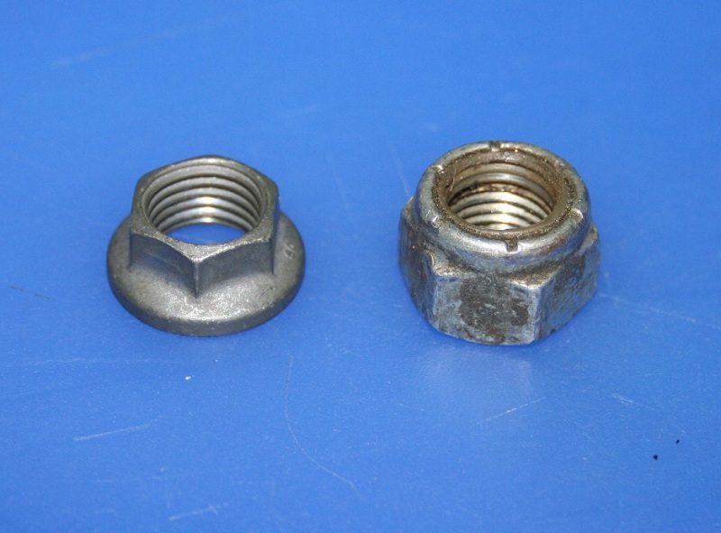
I also have started getting the various fasteners I will need together, I don't like using Nylocs, especially as they still seem to be regularly used near heat sources such as brakes and suspension parts.

I am using K nuts which are aerospace locking nuts, they also have the advantage that they are much smaller in size and for things such as the track rod ends which tend to touch alloy wheels gives a useful couple of mm extra space.

Image

Cheers

Cheers
Post Reply