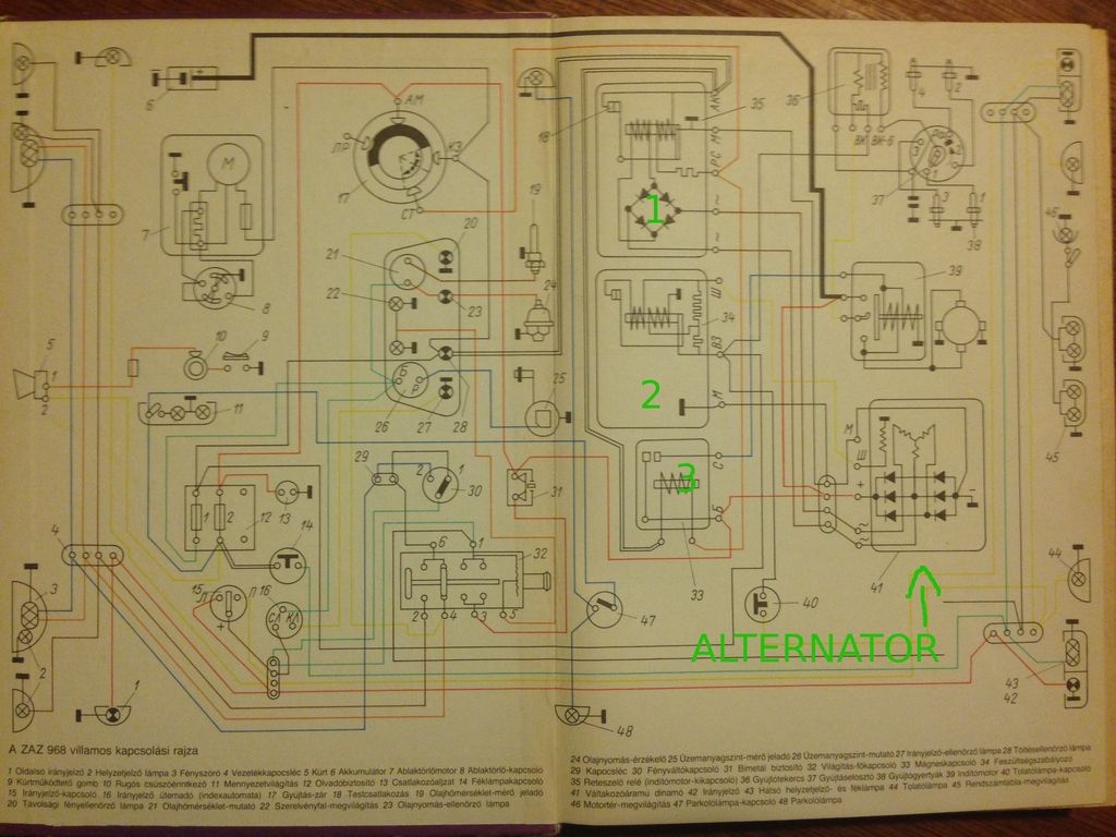
The circuit diagram shows the alternator and 3 little boxes labelled 1, 2 & 3 for the purposes of this post. I can cope with 3 myself, it is simply a starter relay between the ignition key and the starter solenoid. However, after that, I get a bit stuck.
Questions:
Is the "alternator" an alternator and not a dynamo?
Any idea why the third alternator phase doesn't go through the internal diodes and is instead routed to the rectifier circuit in box number 1?
There are 2 coils in the relay part of box 1. one energised by the ignition, the other comes from the diodes.
Do they both need to be activated to operate the relay, or only 1 of the two?
Any idea what the function of this box number 1 is?
What's the little square wave component symbol in boxes 1 & 2?
Is one of these boxes a regulator?
Can anyone explain in stages how it's supposed to work? Something like: Turn on ignition, 1 closes, 2 is open. Engine is started, 1 and 2 are closed while charging, when batter charged, 1 opens, etc.??
I almost forgot to explain my problem! I don't think it's charging right. Alternator light stays on. When running, I do see a small increase in voltage, but I only read 12.9V on my volt meter. If I turn on some accessories, it's back down to about 12V.
Thanks,
Paul.